
DNV’s concerns
Given the field failures, we are concerned as to whether enough testing or the ‘right’ type of testing is being performed. Thus, we raise the following questions:
A. Given that the short mounts on a large area module with thinner frames is pushing the design to the limits, and that the glass has become part of the load bearing structure, do we need to increase the samples tested to account for the higher variability of glass fracture and to increase confidence?
B. Is SML testing the right test? As the stresses on the module approach the design limits, do we need to account for other sources of strain? Some mounts mechanically connect adjacent modules, and any bending of the torque tube will compress or pull on the module frames.
A. Glass fracture variability
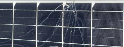
In our engineering judgment, the large-area modules with 35 mm and thinner frames, increasingly relies on the glass itself as a structural component. This was pointed out to us in a conversation with Colin Sillerud at CFV Labs. In his presentation at the 2023 IEEE PVSC, Colin showed preliminary evidence that the shorter the tracker mount, the higher the variability in pressure at breakage in SML testing. This would be consistent with the idea that the glass is carrying a larger portion of the loads applied to the module. To understand why variability would increase, and why testing one module in an SML test is inadequate to represent whole fleets of modules, we need to understand something about the mechanical properties of glass and glass fracture.
Glass is an incredibly strong material, at least in theory, were it not for one significant vulnerability: cracks or microscopic flaws under tension. Such flaws on the surface or most often on the edges of the glass become stress concentrators as illustrated in Figure 2. In practice, such microscopic flaws limit the typically observed tensile strength of glass to be orders of magnitude lower than the theoretical strength derived from the silicon-oxygen bond strength. What makes such flaws so lethal to glass is the stress concentration at the crack tip which, in brittle materials, is atomically sharp. In ductile materials, stress concentration at the crack tip results in plastic deformation of the material surrounding the tip, causing the crack tip to blunt, thereby reducing the stress concentration around the tip. This leads to slower or complete halting of crack propagation. Brittle materials, on the other hand, do not undergo plastic deformation and therefore maintain the atomically sharp crack tip, enabling the crack to propagate rapidly. Consequently, the mechanical properties of glass under tension (e.g. outer surface under a bending strain) are highly unpredictable due to the unknown distribution of surface flaws. The fewer and smaller such flaws, the stronger the glass can be, but it is not generally feasible to completely eliminate microscopic flaws in high-volume glass production, nor to prevent such flaws while in service (i.e. wind-blown sand).

Figure 2 Stress concentration at the tip of a crack in material under tensile stress [2]
Successful use of glass in automobiles, cookware, and coffee tables lies not in eliminated surface flaws, but in avoiding surface tensile stresses altogether. A large compressive stress is created on all surfaces of the glass through a process known as tempering which is performed during the cooling of hot glass. By rapidly cooling the glass surfaces first, before the center of the glass has cooled, a situation can be created where the outer surface contracts and hardens, while the center remains hot and malleable. Because the center is still malleable, it can accommodate the shrinking and hard outer shell. Subsequently, when the center then cools and contracts, it places the already hard surfaces under compression to such an extreme extent that any potential flaws in the surface only experience compressive forces even when the glass is subjected to a bending strain (up to a point of course). As the glass becomes thinner, tempering becomes more challenging to create the large temperature gradient needed to keep the center hot while cooling the surface. Thus, 2.0 mm glass used in dual-glass modules is only heat-strengthened where the compressive stress on the surface is lower than that of fully tempered glass.
Where the limit of glass fracture occurs under stress, now depends not on the theoretical yield strength of glass, but on the distribution in size and density of flaws as well as the degree and uniformity of tempering. Thus, when evaluating the load limits of large area modules, the designer must consider, not only the modulus of glass, but some measure of edge and surface finish and temper. In practical PV manufacturing, there can be considerable variability in glass tempering, surface finish, and bulk quality, especially from different glass vendors. Jean-Nicolas Jaubert of PVEL commented that there exists a mindset of “glass is a commodity material” and pointed out that “most of the glass suppliers don’t have well established, quantitative processes for assessing their product mechanical behavior.” We are aware that some module manufacturers do perform sample testing on incoming glass batches including tempering measurements and 4-point bending tests. While such controls may place a floor on low quality glass, the market doesn’t know which manufacturers perform such in-coming material controls. Even with these quality controls, glass fracture is considerably more varied than metal failure.
Due to this variability, Tristan Erion-Lorico at PVEL described that some savvy buyers are running SML followed by dynamic mechanical load (DML) testing of 1000 cycles of ±1000 Pa with 25 or more modules. Interestingly, Tristan reports that some module’s glass broke during the DML test after passing the SML test. We feel this observation highlights the need for the industry to undertake additional studies of failure mechanisms and testing protocols as glass has become a structural component of the module.
An additional study that we would propose to the industry – module and tracker manufacturers – is to undertake a statistically large test of 50+ modules (with known glass manufacturers), using SML testing with ‘loading to failure’ for a particular mount. To first order, such tests could be performed even on modules without cells and thus focusing on the variance and influence of glass and mechanical failures. Of specific interest would be to gauge the variance in ‘maximum load at failure’, and therefore, the required safety factors to stay far from failures.
B. Adequacy of SML test
The typical ~2 m2 module has been used as a basis for many commercially available mounting systems currently in the market. These mounting systems would potentially require more rigorous testing procedures than currently practiced in the solar PV industry for the large-area format modules of >2.5 m2. As modules are approaching their design limitations, additional stresses coming from the asymmetric wind loads, tracker flexibility, and compounding installation tolerances may need to be accounted for. In other words, in DNV’s view, the simplified test setups for SML testing are not adequately accounting for additional stresses and the safety factors currently included with SML tests may not be adequate to provide enough design margin for such contributing factors.
B.1 Asymmetric loads
The SML test loads the module with a uniform load across the entire module. However, many in the PV industry note that the wind load on the module may exert an asymmetric load, meaning the load is much higher on the leading edge of the module than on the middle or trailing edge. This makes the modules especially vulnerable because, with the 400 mm mounts, the leading edge of the tracker, experiencing the most wind load, is cantilevered and not supported. Moreover, the wind load distribution along the module changes with tracker tilt as shown in Figure 3. Some manufacturers are starting to work with wind tunnel consultants to understand how the modules are actually loaded due to wind. They then use such data to asymmetrically load the modules to create a more realistic loading scenario based on their specific stow strategy.

Figure 3: Asymmetric loads on a module at different tracker angles [3]
Anecdotal reports indicate that asymmetric loading does reproduce the failures observed in the field. Cherif Kedir at RETC notes that some customers perform asymmetric SML followed by dynamic mechanical load test (DML) tests that successfully replicated observed field failures. Colin Sillerud at CFV has also conducted non-uniform loading tests which have replicated field failure modes. DNV would also propose a wider study on replicating field failures with symmetric and/or asymmetric load tests. This clearly would require a survey of typically confidential field failures and maybe the purview of a government lab like NREL or Sandia.
While we encourage the development of new ‘compatibility testing’ standards which may include asymmetric loading, we are concerned about how to quantify the asymmetric load capability such that this information can be used in the system design. A second concern is that modules are being installed today while a new asymmetric load standard may take years to standardize. (Are there possible correlations between SML testing and asymmetric load testing that could be used as a proxy immediately?)
B.2 Full testing
As the edge of the design limit is approached, all aspects of the installation are important. When performing the SML tests in a lab, flexing of the torque tube in torsion and in heaving, separation of piles, and play in the bearings are not similarly considered. These factors may add to the stress in the modules, whether bolted or clamped. DNV proposes a comparison between the standard lab SML testing and a test including all tracker components. In addition, only a single module is typically tested for 1P trackers (or 2-module setups for 2P), however, this type of testing only exposes end rails/clamps to required loads. Mid-clamps and mid-rails, which are typically a vast majority of module-to-racking connections in the field are not part of the qualifying tests.
Conclusions
We at DNV are noting elevated risks and field failures associated with large-area modules mounted on narrow tracker mounts. While we assume manufactures are performing load analysis and testing, we note that either no evidence or only one SML test is provided as evidence of ‘compatibility’. This comports with discussions DNV has had with testing labs RETC, CFV, and PVEL, who have independently raised concerns regarding large-area module field failures. We also note that some manufacturers further distance themselves from any liability for module breakage with language in guidance documents. As the area increases and the frame rails become thinner, the glass itself takes on an increasingly significant load bearing role. Glass, being a brittle material, will have a significantly higher variability in failures, requiring higher numbers of modules to undergo SML testing and increasing glass quality controls for tempering and edge finishes. Additionally, as the design is pushed to its limits, additional stresses in the full system may need to be accounted for which are not presently included in the standard SML test, such as asymmetric loading or tolerance stack-ups during field installation. DNV is advocating a broad discussion across the PV industry to address these issues.
Acknowledgements: We are grateful for the very informative discussions with Jean-Nicolas Jaubert and Tristan Erion-Lorico at PVEL, Colin Sillerud at CFV, and Cherif Kedir at RETC.
References
[1] Daniel Chang, RETC, in PV Magazine Webinar, August 30, 2021 https://www.bigmarker.com/pv-magazine-events/pv-magazine-Webinar-Module-wind-load-resistance-Standards-vs-reality?utm_bmcr_source=video
[2] https://www.comsol.com/blogs/singularities-in-finite-element-models-dealing-with-red-spots/
[3] Scott Van Pelt, GameChange Solar in PV Magazine Webinar, August 30, 2021 https://www.bigmarker.com/pv-magazine-events/pv-magazine-Webinar-Module-wind-load-resistance-Standards-vs-reality?utm_bmcr_source=video