Floating Substations: the next challenge on the path to commercial scale floating windfarms
Although essential to the development of commercial scale floating offshore wind farms, floating substations have not received the same degree of attention or full-scale prototypes as their turbine counterparts.
Now that the first commercial floating windfarms are about to enter the development phase, however, the industry needs to pay particular attention to this critical element.
Floating wind is attracting increasing investment and public policy support because it can access the 80% of offshore generation potential that is in water depths exceeding 60 meters. These deeper waters tend to be further offshore, where wind is typically more consistent, but where bottom-fixed offshore wind support structures are less feasible technically, logistically, and economically.
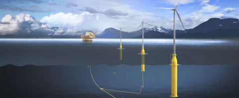
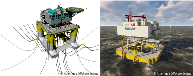
In recent years, development of floating offshore wind technologies has been swift, with many concepts emerging. Following the successful deployment of prototypes and demonstration projects, the industry is now transitioning rapidly to commercial projects. However, while demonstration projects generate limited amounts of power that can be exported directly to shore, a commercial scale project will require an offshore substation (OSS). The OSS will host a step-up transformer and the equipment necessary to export power in high voltage (HV). The only floating OSS in the world was installed in 2013 in Fukushima, Japan, and is connected to 3 turbines. The Fukushima OSS handles a total of 16MW and exports power at 66kV, which is not comparable to a commercial scale windfarm.
A floating windfarm would typically be installed in depths exceeding approximately 60 m, where a bottom fixed monopile or jacket would not be economically relevant. For an OSS, the critical depth for a bottom-fixed foundation could be economically competitive as deep as approximately 100m, a depth not unusual for Oil & Gas fixed platforms. For the first floating wind farms, where water depths allow, bottom fixed substations (using tall jacket foundations) could limit the risks and costs inherent to new technologies such as high voltage dynamic cables. In places like California, however, with depths greater than 500m within the planned offshore wind call areas, bottom fixed substations are not an option.
Different concepts
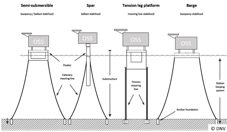
The different concepts foreseen for floating OSS foundations are similar to designs utilized for wind turbines: semi-submersibles, tension leg platforms (TLP), barge, or even spars. The barge, semi-submersible, and spar buoy are moored to the seabed with chains, steel cables, or fibre ropes connected to anchors. A TLP is vertically moored with tethers or tendons, these being the “tension legs”. Very strong cables, pipes, or rods link the TLP’s legs to seabed anchoring. Across all types of floating foundations, different anchor types can be used depending on the type of mooring system, soil condition, and expected environmental loads.
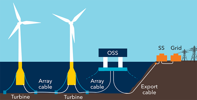
It is tempting to consider the same type of floating foundation for the both wind turbines and the OSS, thereby taking advantage of synergies in design, construction, installation and even O&M. However, this synergy is difficult to achieve due to the different constraints of on OSS. First, the OSS topside can be significantly heavier than a wind turbine (between 2000 to 4500 MT for HVAC and even heavier for HVDC, compared to ~1200MT for a 12MW wind turbine assembly), and the weight distribution is also very different, with a lower center of gravity for the OSS. These factors have a direct impact on the floater’s stability and seakeeping, requiring different floater dimensions or even a different concept altogether. Second, an OSS has a multitude of connected subsea cables. A typical project arrangement could have more than ten array cables and at least one export cable connected to the OSS. This dense subsea cable configuration is very sensitive to broad displacements, and excursions of the OSS too far from its original position may damage the cabling. Therefore, since the OSS and the export cable are single points of failure for the whole windfarm, the mooring system requires special attention in order to provide efficient station-keeping and a high level of redundancy in the case of mooring line failure.
A combination of proven technologies and innovations
Even though the TLP configuration can significantly reduce the heave and roll movements of an OSS structure, all floating platforms will eventually move. This dynamic behavior of a floating installation is a design challenge as compared to fixed OSS. And while most components of a floating OSS are proven technologies coming from the Oil & Gas or Maritime industries, two issues that require considerable innovation are: the subsea dynamic high voltage cables and the high voltage equipment.
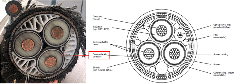
To link the floating OSS to the shore, the HV export cable needs to be “dynamic,” as it will connect a moving structure (the OSS) to a fixed element (the seabed). Unlike standard HV subsea cables used for bottom-fixed OSS, the dynamic cables must be able to accommodate the extreme displacements of the OSS during storms and have sufficient fatigue endurance to handle a lifetime of cyclic movements (>20 years). This kind of cable exists for voltages up to 66kV, but are still under development for the higher voltages required for power export in commercial-scale projects. One of the primary challenges faced by cable manufacturers is finding an alternative material to the lead sheaths surrounding each cable core. The lead sheath protects cable cores from moisture ingress but has poor fatigue endurance.
The other element that is new to installation in a dynamic environment is HV equipment, especially the main power transformer and the gas-insulated switchgear (HV GIS). Although most of the utility systems and medium voltage equipment have proven their reliability in the Oil & Gas and Maritime industries, the HV GIS and power transformers currently in the market have not been designed for the repetitive accelerations anticipated onboard a floating OSS. The equipment is typically designed for seismic motions, but this is not directly transferable to floating conditions given that the movements of a floating structure have larger amplitude and a many more fatigue cycles. The movements could, for instance, provoke oil sloshing in the transformer’s compensator tank, or deteriorate the gas seals of the HV GIS, causing gas loss. New innovations to address the dynamic cable and the HV equipment need to be qualified and tested in real environments before being implemented on commercial-scale projects. To gather sufficient relevant data, this testing phase has to be performed during a significant duration which will impose a delay between the development of a new product and its industrial implementation.
Conclusion
Like floating wind turbines, floating OSS require a number of innovations, each bringing additional risks and costs, especially for pioneering projects. There are ways to mitigate the risks inherent in a floating OSS, thereby providing sufficient confidence to developers and investors. Testing and certification of the critical components will ensure both that the designs are based on best industry practice and that the components meet their design criteria, thus reducing risk of failure. Given the expected schedule for the development of the first commercial floating wind farms, the construction of a full-scale OSS prototype might not be feasible in a relevant timeframe and could be difficult to finance. However, each critical element can be tested individually with appropriate testing techniques such as model tests in basins or dynamic test benches.
Another means to mitigate risk is to implement a high degree of remote monitoring of the OSS to guarantee equipment availability and prevent catastrophic failures. This condition monitoring can be applied to the mooring lines, the cables, the HV equipment, or any other critical elements. In addition, to prevent catastrophic failure, this monitoring will allow for predictive maintenance and thereby reduce O&M costs.
Combining expertise in bottom-fixed offshore wind, Oil & Gas and power transmission, DNV has taken a leading role in developing floating wind technologies. Proven guidelines on structure, stability, substation design, and position mooring are already available, and cutting-edge monitoring technologies have been developed, such as Smart Mooring, a machine learning system used to detect mooring line failures. DNV is also initiating a Joint Industry Project (JIP) on the floating substations to develop new solutions, standards and recommended practices.
4/1/2021 5:00:00 AM