New design loading condition
The basis for determining vessels’ longitudinal strength is the IACS Unified Requirement URS11/11a. However, this is not very specific and may not reflect owner’s requirements regarding later loading flexibility, requiring vessels to be designed for ballast condition, homogeneous loading, short voyages and ports. Alternate loading conditions, required only “where applicable”, are however critical from a hull girder strength point of view because they generate the most severe still-water bending moments and shear forces. In addition, the IACS rules do not explicitly account for block loading scenarios, tandem crane load cases, deck cargo cases and tween deck loads, which they leave to the discretion of designers and owners. To provide owners and designers with improved transparency and guidance regarding the new IACS rules, DNV GL joined hands with industry representatives to define standard loading conditions for multi-purpose vessels. Combining the operational know-how of both DNV GL and its customers, the loading conditions cover relevant operational requirements for these complex ships.
“DNV GL is the first classification society to issue standard loading conditions incorporating load cases far beyond the scope of the IACS requirements,” points out Jan Rüde, Ship Type Expert MPV at DNV GL. “They include block loading scenarios, tandem crane load cases, deck cargo cases and tween deck loads.” The new loading conditions are outlined in DNV GL rules Part 5 Chapter 1 Section 5 Paragraph 4 “Loads”.
Design envelope curve
The permissible still-water design bending moment and shear force curve which define the minimum and maximum loading limits for the vessel are generated using the loading manual. Typically the designer calculates all design loading conditions as agreed with the owner, then draws an envelope curve overall bending moment and shear force values. The designers then agree on a safety margin to be applied to the envelope curve for the steel structure design. The design envelope curve is the basis for class approval of the steel structure drawings. When the ship construction is finished, the envelope curve is fed into the loading computer for planning the loading of cargo. The challenge is to consider all relevant and critical loading conditions in the steel structure design phase to make sure the ship is strong enough to provide the desired operational flexibility during later operation.
Block loading scenarios
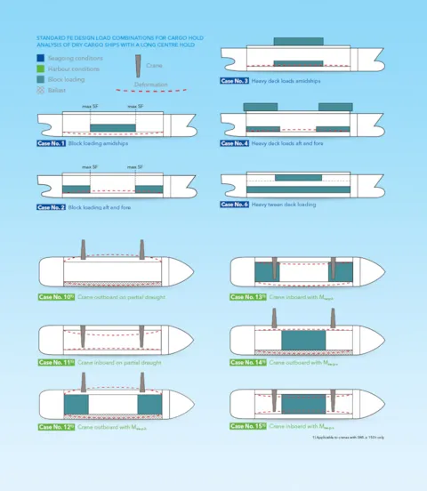
MPVs with a very long cargo hold are often equipped with a re inforced inner bottom designed for a high uniform distributed load such as 20–25 tonnes per square metre. In practice, however, a block load will typically cover only part of the inner bottom, leaving other parts without load. A heavy block load will typically result in excess weight in the loaded parts and excess buoyancy in the empty parts. It should be placed where it creates the most critical conditions from a hull girder point of view. Placing the load block in the middle of the hold creates the worst-case global sagging moment for the hull structure (Case No. 1). Splitting the load block into two units and placing them at the aft and forward ends of the hold results in the worst-case hogging moment (Case No. 2).
Hatch cover and tween deck design
Most cargo vessels have weather deck hatch covers designed for loads as defined by the Load Line Convention, i.e. approximately three to four tonnes per square metre. However, MPVs often have heavy pontoon covers for carrying heavy project cargoes on the weather deck. These loads generate maximum transverse forces in rolling conditions in beam seas and are critical for the transverse side structures (Case No. 3). Here again the load may be centred amidships or be placed at opposite ends (Case No. 4). In addition to weather deck covers, MPVs are typically equipped with heavy tween deck panels capable of handling loads from five to seven tonnes per square metre. The tween deck panels rest on pads integrated into the hull side structure at various levels. The resting pads are exposed to high vertical forces in a magnitude of 100 to 120 tonnes. This loading scenario is critical for buckling of the longitudinal bulkhead under the support pockets and is reflected in Case No. 6.
Cranes complicate the picture
In addition to seagoing cases, it is also necessary to consider crane loading cases for heavy-lift MPVs when operating in port. A heavylift MPV is normally designed for tandem operation of two cranes lifting cargo in and out of the ship. These scenarios are covered by Cases No. 10 to No. 15. A particular challenge for a long cargo hold in combination with heavy-lift cranes integrated into the side structure of the vessel is how to evaluate and limit the inward and outward deflection of the hold structure.
The crane loading cases defined by classification society DNV GL represent the most severe conditions, providing the hatch cover designer with valuable input regarding expected coaming deformation.
“The new DNV GL rules on Standard Loading Conditions for Multi-Purpose Vessels represent a major milestone for us and our customers,” says Rüde. “They benefit both ship designers and owner’s who must jointly define the design loading conditions for planned newbuilds at an early project phase as they will ensure that the vessels will have the intended operational flexibility whilst taking into account the impact on production costs.”

Get regular MPV insights!
Don’t be left out. Join the many others and sign up today to receive the latest insights.
sign up